FX-888 LED Mod
To mark the the USA’s daylight savings time switch, I spent some of this evening being super productive - modifying my FX-888 indicator LED!
These are really great soldering stations - nice temperature control, plenty power for most jobs, decent ergonomics, tips are cheap and easy to find, and they aren’t too expensive. That said, the FX-888 has a significant design flaw: the only visual indication that it’s switched ON is a red LED on the front, that lights only when the iron is actively heating. So, when it’s idle, there generally isn’t any visual indication at all!
I’ve been meaning to improve that LED for a while, following accidentally leaving the iron switched on a few times. My original plan was to just rewire the it so the LED stayed on continuously when the station was switched on - I don’t really need to know the state of the thermostat after all. Then, I saw a video Dave from EEVblog did on modifying his FX-888 with a bi-colour LED - nice idea! I found myself in Jaycar this morning for some other parts, so picked up a couple red-green LEDs to follow his lead.
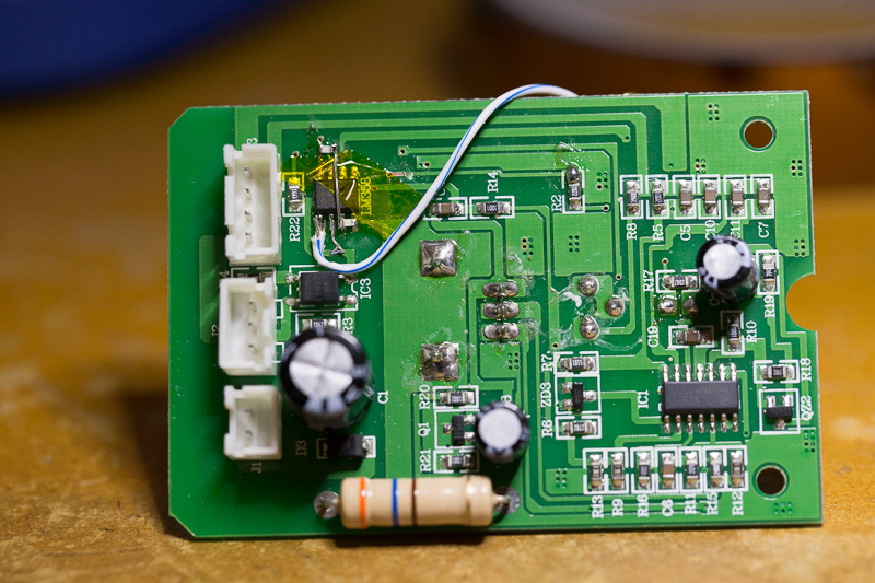
As Dave discusses in his video, there are a couple types of these LEDs, I bought common cathode ones. It also turns out that my control PCB is completely different - likely not an original Hakko part (these are commonly counterfeit…). My board is completely analogue, and they kindly left half of an LM358 opamp not only unused, but not even properly terminated!
The original design uses half of that LM358 as a comparator to drive what looks like an opto-triac, and the LED takes off from the same output. That signal is active low, and the LED goes between it and the + rail. So, I wired up the green side of the LED between the power rails, adding a resistor between it and +, wired up the other half of the opamp as a comparator to make an active-high output for the red side of the LED, and connected the common cathode to ground via the original LED current limiting resistor.
Easy peasy! Now the LED is green when the iron ON and at temperature, and orange while heating. All it took was one cut trace, a couple jumpers, and three resistors: