Scoreboard
A small group from pact have been spending an hour or so each week at the makerspace for the last several weeks, learning to solder and learning a little bit of electronics too. They’ve finished their first projects, 555-based LED flashers, and are itching to do more! We’ve had an idea to make a scoreboard for their pickup basketball group as the next project, which seems quite popular. The scoreboard will involve a bit more soldering, plus some thinking about design, some programming, a little woodworking, some cleaning, and who knows what else.
I’ll be designing the electronics and doing most of the programming, and would like to document the process and design here. My plan is to update this post as the project progresses, including linking to eventual github repositories for any PCB designs, electronics, etc that go with the project. It’ll all be open source, so anyone interested can replicate or iterate our design. For me, this is a nice excuse to take a couple of my favourite pieces of software - FreeCAD and KiCad - out for a spin, to accomplish a couple peripheral goals, and maybe to help some folks learn some good stuff and have a good time too!
Project Goals
First and foremost, we want a project that is easy to solder together, involves some steps that require a bit less fine motor control than soldering, and that will result in something interesting. Secondary to those goals, we want a functioning scoreboard.
As the guys cleaned off the old signs, I stuck a few 5mm LEDs on a piece of junk PCB, and hooked them up to a battery so we could figure out an appropriate spacing between LEDs. My initial thought was that 4 LEDs for each segment would look good, but we ended up deciding on 6 LEDs per segment. We also came to the conclusion that 2 digits for each team would be fine, so that means 4 digits * 7 segments/digit * 6 LEDs/segment = 168 LEDs.
After some talking and thinking, I came to the conclusion that it would be good for the “business logic” of the scoreboard to be done in the Arduino environment, since that would provide a good learning environment. At the same time, I don’t think it would be great to have each segment be controlled directly by Arduino - too many wires to get mixed up, and the Arduino code might get a little too complex. I settled on an architecture with the Arduino handling the buttons and driving each digit, which is in turn controlled by a small ARM microprocessor.
Personal Goals
I spend a lot of my work time reading embedded and application level code, thinking about electronics, occasionally making things work. So, while in some sense this is just a “toy project”, there are a few things I’d like to accomplish with it:
- For personal projects involving microcontrollers, I’ve been using AVRs since I moved on from the BASIC Stamp a decade or so ago. I’d like to get my personal toolchain moved over to ARM. While I’ve used some mid size ARM chips for work projects, and the BeagleBone for hobby projects, the modern ~$1 ARM micros are new to me.
- Another project could use for a little I2C slave to UART bridge.
- There’s a cool looking KiCad-FreeCAD collaboration tool that I want to play with.
Big Picture Considerations
At the moment, this section is a bit of a brain-dump of considerations that I want to incorporate in the final design.
- I like the idea of driving the finished project through an Arduino Uno compatible board - Paul has been distributing them to kids around Dunedin as part of a kit, and I think this project could provide a good talking point for what’s easy to do with Ardunio.
- Most of the soldering needs to be through-hole, and the PCBs need to have silkscreening that’s easy to read.
- Wiring needs to be simple. Given the scale of the display, I imagine that we’ll have a PCB per segment, but I think running a pair of wires from each of 28 segments to a central controller would be a bit too tedious. So, my current thinking is to make each digit more-or-less self contained.
- The finished scoreboard should be reasonably durable, as it’ll be transported to the basketball court where it’s used.
- Expanding on 4 - it should run off a rechargeable battery.
- The 3D printers at makerspace are quite popular, perhaps we could use them for some parts of the project?
If each digit is self contained as in point 3, then that opens up possibilities for other permutations of the same design. For example, a traffic light could be constructed from similar components.
Components
The Board
A happy coincidence happened with this project last week. D and I had briefly discussed this scoreboard idea before, but hadn’t made time to sit down and think about it too much. D and the guys were on the way down to VCW to finish up their 555 projects, but had been waylaid at the last minute.
Concurrently, the VCW was having a bit of a clean out, to facilitate some repair work on the building, so I was helping out in the mean time. As we were cleaning up some dirty old pieces of MDF, polycarb, and whatever else from a corner of the building, and found a weird old contraption!
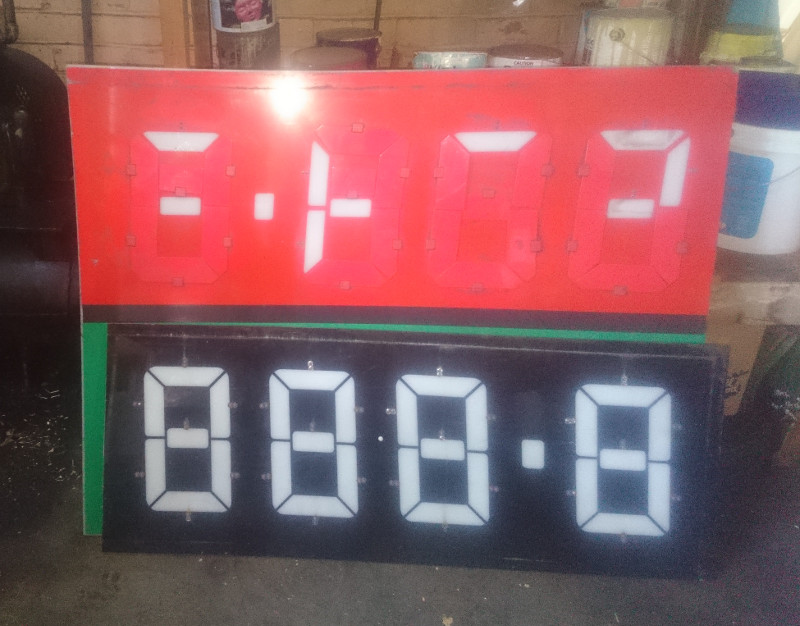
It’s a sheet of translucent plastic maybe 1x1.5m, painted black on one side, except some big 7-segment digits masked out from the paint. On the other side are hinged baffles to cover the digits. At the time, I figured it was an old scoreboard! Perfect. Looking at it a little closer, there are two big numbers, one red and one green, formatted like 8.888, so it’s more likely a sign from a petrol station. But, we can use it either way of course.
The main part of the scoreboard is a solid sheet of plastic, and the LEDs will need to be mounted through hole on the PCBs. So, there will need to be some mounting hardware between the plastic and the PCB - I’m currently leaning towards 3D printed washers which might clip on to the PCB and attach to the plastic scoreboard with adhesive.
The [Printed Circuit] Boards
The PCB design files live in their own repo.
Dirty PCBs, my go-to supplier of such things, has really good pricing on 10x 2-sided PCBs that fit within 10x10cm, so I’d like to keep our design in that envelope. There will be 28 segments required, so a pack of 10 boards will work if it can be broken in to ~3x10cm per segment.
Easter weekend, I spent a few hours on the circuit design, and had a first cut of the schematic drawn up. The workflow was fairly straightforward - I went to Digikey and searched for ARM M0+ microcontrollers, in stock, quantity 10, sort by price. ATSAMD10C13A-SSNT was the winner. That’s a 48MHz 32 bit computer, with all kinds of interesting peripherals, at $1.03USD in single unit quantities… Brings new meaning to “cheap as chips”!
Then, there were a few sundry pieces to track down based on what we have on hand in Dunedin - some FETs for switching the LEDs, a linear regulator to power the microcontroller, etc. Those all came from one vendor on aliexpress - total for 400 LEDs (I don’t know if they’ll want red or green, so got 200 of each), current limiting resistors, a hundred-odd transistors (need 9 per digit) and regulators (1 per digit), a spare Arduino clone just in case:
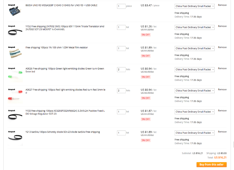 .
.
Once the parts were picked out, it was off to KiCad (by way of github to start a new repo) to start drawing. The microcontroller and voltage regulator I picked weren’t in the part library, so those took a few minutes to add. It could be my imagination, but I think the workflow for adding parts has gotten just a little easier - still certainly room for improvement, but not bad! The layout has been done in fits and spurts over the last week or two, with occasional small changes to the schematic, and I finally ordered some boards 3 May.
The PCB design is fairly straightforward, I’m impressed by how simple the SAMD10 interface seems so far - very few external components or connections are required. There are just a few sections to the schematic:
- The PCB will be split in to three pieces; each has 6x 5mm LEDs, and is one of 7 segments needed to make a digit. One of the three pieces of each PCB can optionally be populated with the controller for its digit.
- Power is supplied (from a 6V battery) through a connector and reverse-polarity-protection FET, and regulated to 3.3V for the microcontroller with a linear regulator.
- Since we might be interfacing with a 3.3V or a 5V controller, and I was placing jellybean FETs anyways, there’s a proper I2C level shifter.
- LED segments are driven via FETs, with the gates pulled down just to prevent flickering or whatever on powerup.
- Six of the gate lines for the LED drivers are also used on startup to read 3 solder jumpers, to set the I2C slave address of the segment. That way, we can have up to 8 of the digits connected to the same I2C bus.
- There’s a “heartbeat” LED - a trick I picked up at an old job. The heartbeat is slowly blinked continuously. It helps with troubleshooting - if the heartbeat is going, then you know at a glance that the microcontroller has power and a clock. This one was a little more tricky to implement than usual, since I’m sharing the microcontroller’s SWCLK programming pin with the LED. It’ll be important to make sure the firmware waits a few seconds at startup before setting that pin to output mode, otherwise it would be easy to “brick” the chip since it won’t be programmable when the pin is an output.
The boards will hopefully look something like this:
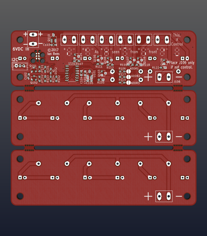 .
.
Firmware
I made the firmware that runs in the microcontroller for each digit, and plan to have have the pact folks make the Arduino program that controls the whole scoreboard. It took a while for the PCBs for the digits to arrive, and I guess it will still be a few weeks before the Arduino program is working satisfactorily. So, I wanted a way to simulate the scoreboard in the mean time, and put together a little Arduino program to drive an I2C-connected LCD using an interface like the digits will provide: source.
The first cut of the firmware seems to work well, in the limited testing I’ve done so far. My learning curve with Atmel/Microchip’s START platform wasn’t too steep, though I think it’s a bit too heavy for my usage but still required a bit of hackery to get one of my side projects (the I2C slave - UART bridge mentioned in Personal Goals to work properly.
As a tangental rant - I think the goal of a nice cross-platform toolkit for embedded systems is a noble one, but probably the effort on the really low level stuff would be better spent on documentation for the hardware. It seems like every time I encounter a library like the ASF, I end up needing to make modifications to either it, which defeats the purpose a bit…
Power Supply
Our scoreboard will need to work from battery power, for a few hours per charge. It takes ~6V DC input, and will draw about 20mA per string of LEDs, of which there could be up to 84 illuminated, so that’s roughly 1.75A at “full noise”. Current thinking is that a smallish 6V “gell cell” will be a good bet, with an off-the-shelf charger.
Initial Assembly
Somewhat surprisingly, the first PCB design results in a working segment! I assembled the first control segment and one of the controlled segments at home and used them for the first round of firmware development. There are a few issues with the original design, which I might get around to fixing at some point down the line if anyone is interested in making another one of these:
- The Tag-Connect footprint is a bit too close to the IIC and input power connectors
- I’m not super happy with my solder jumper footprint, it seems to take either a fair amount of solder or encouragement to bridge and look nicely. It would probably work better if the dividing line between the two pads were longer, maybe more like an (angular?) yin and yang symbol.